Clap on clap off switch circuit diagram using 555 timer ic Clap switch circuit using ic 555 timer without timer, 59% off Clap switch circuit diagram using ic 555
Clap Switch Circuit Diagram using IC 555
How to make clap switch circuit using 555 timer ic Clap switch circuit electronic project using 555 timer Dancing light using 555 timer
Clap switch circuit using ic 555 timer & without timer
How to make clap switch circuit using 555 timer icBuilding a clap switch circuit (using 555 timer and bc547b transistor Constructing a clap switch circuit using 555 ic and relayClap timer project.
Clap icClap switch circuit diagram without ic Clap 555 timer ic transistors transistor bc547 schematic electricaltechnology automatic lab arduino irrigationClap on clap off switch using 555.

Clap electricaltechnology
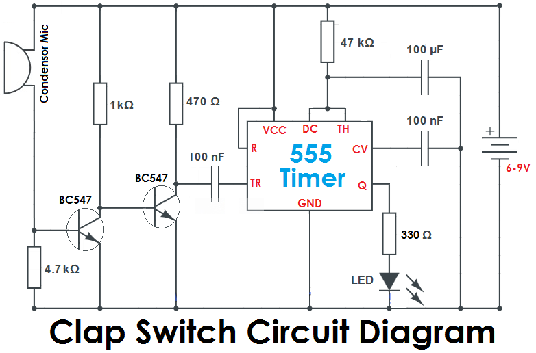
Circuit diagram of clap switch using 555Clap switch circuit using 555 ic and bc-547 555 clap switch using off ic components required theorycircuitClap switch circuit using 555 timer.
Simple clap switch circuit using 555 timerClap switch circuit electronic project using 555 timer 555 timer circuit using light dancing circuits diagram easyeda chip pcb pulse 555timer ne555 projects electronics time astable lm555 modeClap switch using op-amp and 555 timer ic : 6 steps.

Simple clap switch circuit using ne555 precision timer ic
Timer ic block diagram working pin out configuration data sheetSwitch clap circuit using 555 timer circuits electronic electroniq Clap on clap off switch using 555Switch clap circuit timer using simple.
Clap switch circuit diagram using ic 555Clap switch circuit using timer hackaday io Electronics circuits: clap switch using 555 icClap switch circuit 555 using timer ic electronic project electronics projects led mini bc diagram capacitors components resistors simple sound.
Circuit switch clap diagram 555 using ne555 sound ic timer projects relay clock ic2 transistor electronics each output generated used
Clap timerHow to make simple clap switch automation Clap switch using ic555 timerClap switch off circuit diagram 555 using ic timer electronics circuitdigest projects automation sound electronic circuits mic condenser switching dc.
Clap circuit switch diagram circuitdigest electronic arduino power sound sensor project circuits block condenser gif board amplifier 555 using icClap switch circuit diagram using ic 555 Clap switch using timer circuit transistorHow to make a simple clap switch using 555 timer.

Clap switch register log post
Clap sensor light switch circuit diagramClap switch circuit using ic 555 timer without timer, 59% off Clap switch circuit using 555Clap switch circuit using 555 timer.
Clap switch circuit using ic 555Ne 555 based clap switch circuit diagram. Clap switch : circuit, working, advantages & its disadvantages.

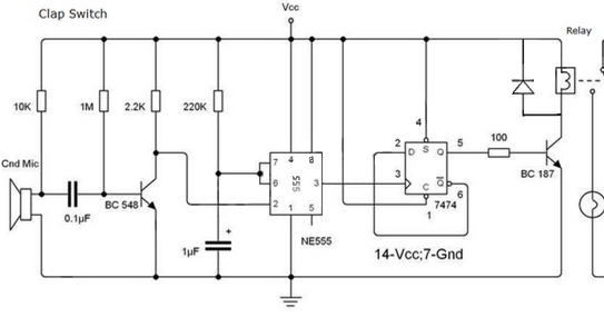
Clap Switch Circuit Using 555 IC and BC-547 | Electrical Engineer

Clap Switch Circuit using IC 555

Simple Clap Switch Circuit using 555 Timer

How to Make Simple Clap Switch Automation - TRONICSpro

Clap-switch-circuit-using-IC-555 - theoryCIRCUIT - Do It Yourself

Clap Switch Using Op-amp and 555 Timer Ic : 6 Steps - Instructables

Clap Switch Circuit Using IC 555 Timer Without Timer, 59% OFF
